Heat Sinkpackages are the first groupThe heat sink chip carrier - lead frame is soldered directly to the PCB. If an IGBT setup is available where the fed-in power loss P L t is known the case temperature T.

Heat Sink Design Calculators Thermal Analysis Software
To select a heat sink firstly thermal resistance of the heat circuit is calculated.

How to measure thermal resistance of heatsink. I present a Thermal Resistance Meter based on Arduino. Heat Sink Thermal Resistance Calculator. For single emitters the case location is defined as the back of the LED package at the center of the thermal pad see Figure 1.
Thermal resistance Heat sinks are rated by their thermal resistance and measured in degrees Celsius per watt CW. Difference in thermal resistance between testing methods is due to the dense fins. The lower the thermal resistance the better the heat sink will transfer heat.
The formula to find the required thermal resistance of the heat sink given by jluciani is basically correct but is missing a term for the ambient temperature Ta. Thermal resistance is defined as temperature rise per unit of power analogous to electrical resistance and is expressed in units of degrees Celsius per watt CW. All of the particle tracks go through the heat sink in the ducted simulation as shown in Figure 4.
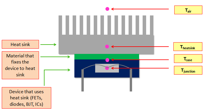
The junction-to-case thermal resistance R th J-C is a measure of how well heat can be dissipated from the die to the package case from which heat is extracted by placing it in thermal contact with an external heat sink. This is due to the heat loss to the environment via. For the selection of the right heatsink the thermal resistance is important.
The thermal resistance of this packages between chip and heat sink is called R thj-c. The following equation can be used to calculate θ CS from the TIM properties. If the device dissipation in watts is known and the total thermal resistance is calculated the temperature.
This can be found in the heat sink datasheet. For emitter arrays where the LEDs are. Tj Rjc Rcs Rsa Pd Ta Where Tj is the maximum target temperature of the junction.
Maximum ambient temperature Maximum case temperature Power output of your RF amplifier. This tool is designed to calculate the heat dissipation and the heatsink thermal resistance required given four parameters. P P power dissipated.
Heat source Q 1500 W Inlet temperature T_in 293 K. In this case the thermal paste is included in the heat-sink measurement and is no longer to be considered separately. You will not be able to calculate the heat sinks thermal resistance as it depends on too many unknown factors.
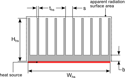
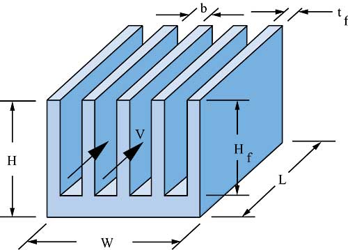
θCS T hickness Area 1 Conductivity θ C S T h i c k n e s s A r e a 1 C o n d u c t i v i t y θ SA specifies the thermal resistance from the base of the heat sink to the ambient environment. P D Power Dissipated 45 W. Of the heat sink is to be determined by measurement the case temperature T c should be used instead of the heat-sink temperature T h.
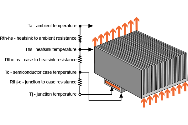
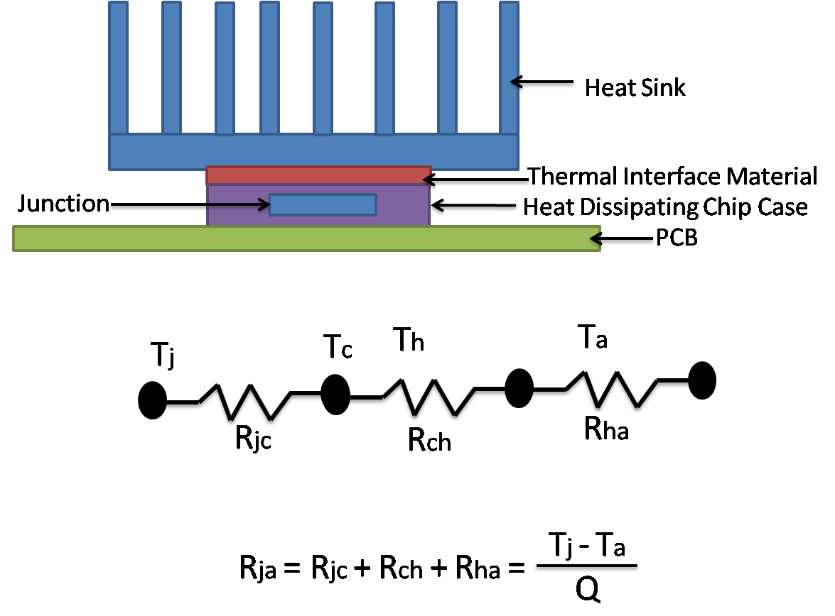
The resistance to heat flow from the junction of the heat generating component through the casing thermal interface material heat sink and finally to environment is represented by the thermal resistance circuit shown in the diagram below. Figure 1 Heat Sink - vs. Mathematically thermal resistance of a body is equal to the ratio.
Therefore it is advisable to calculate the requested thermal resistance for the demanded heatsink in advance. The following equation is used to calculate R hs the thermal resistance of the heat sink. Similarly thermal resistance of a heat sink measures the heat transfer efficiency of a heat sink in a thermal circuit.
T J T J junction temperature. Calculation of the thermal resistance The thermal resistance of a heatsink is calculated in KelvinWatt KW. R1 R 1 thermal resistance of device junction to air if no heat sink or thermal resistance of heat sink.
For the suitable heatsink. Thermal Enhanced Package Types SMD-Package Properties for Power Applications There are two basic groups of packages. How to Calculate Thermal Resistance of a Heat Sink in an Enclosure The structures in the enclosure do not significantly obstruct the movement of air flow throughout the enclosure Air flow through the heat sink is not restricted due to the lack of ventilation in the enclosure Radiation exchange.
Airflow goes around the heat sink in an unducted test as shown by the particle tracks in Figure 5. Rcase R c a s e thermal resistance of device junction to case. While the hardware is straight forward the Software was a pain until I got the right idea that made i.
Thermal Resistance TemperaturePower Dissipation You have to go further than a simple selection with thermal resistance value. The best approach for determining the thermal resistance is to make actual temperature measurements under realistic conditions as suggested above. T J P Rcase R1 R2 T a T J P R c a s e R 1 R 2 T a.
The equation should be. Simulated as a dual heat sink the thermal resistance differs by 12. Heat sink comparison - calculating thermal resistance Using the following specifications we can use our preferred formula to calculate the thermal resistance of both the s-shaped heat sink and our generative heat sink.
Heat Sink Thermal Resistance Calculation Easy Explanation Electronicsbeliever

Thermal Resistance Calculator For Plate Fin Heat Sink
Heat Sink Calculator Electrical Engineering Electronics Tools

Thermal Resistance Network Of Fhs Vc System Download Scientific Diagram

Finned Heat Sink Thermal Resistance Calculation Download Scientific Diagram

Heat Sink Wikipedia
How To Calculate Thermal Resistance Of A Heatsink In An Enclosure Heat Sink Calculator Blog Focused On Heat Sink Analysis Design And Optimization
Heat Sink Thermal Resistance And Size Calculation Heat Sink Selection

How To Measure Thermal Resistance Of Led Emitters And Arrays Part 1 Ee Publishers
How To Select A Heat Sink Electronics Cooling

Heat Sink Thermal Resistance Calculator

Choosing The Appropriate Heatsink For An Application By Fischer Elektronik Led Professional Led Lighting Technology Application Magazine

Mechatronix Thermal Calculation
Estimating Parallel Plate Fin Heat Sink Thermal Resistance Electronics Cooling